Individual Assignment

โœ…
Measure something: add a sensor to a microcontroller board that you have designed and read it.

Group Assignment

โœ…
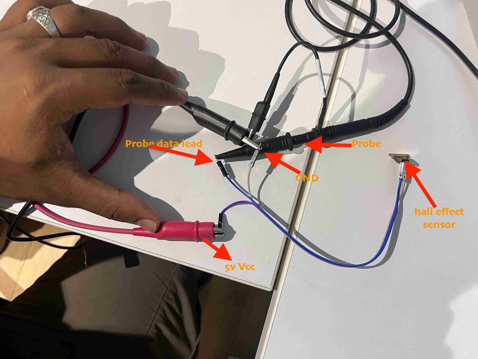
Probe an input device's analog levels and digital signals.

Table of Contents

Hero Shot

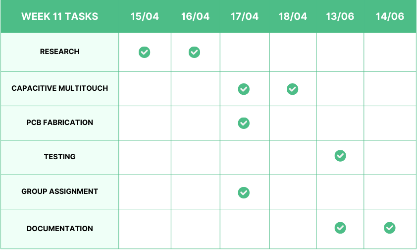
Week 11 Work Plan
๐Ÿ’ก
This week, I decided to try out capacitive multitouch. I am really fascinated by the possibilities of capacitive sensors. Moreover, I am planning to implement this sensor on my custom chess board.ย 
โšก
The chess board consists of 64 squares, so it would be easy to implement below the chess board. This method would be extremely effective, considering its cost-effectiveness.

Step Response

The step response of a system is the output behavior of a system when subjected to a step input. A step input is a type of input signal that changes from one value to another, typically from zero to a constant value, instantaneously at a specified time.

๐Ÿšจ
Follow the link below to learn more about step response.
Step response
The step response of a system in a given initial state consists of the time evolution of its outputs when its control inputs are Heaviside step functions. In electronic engineering and control theory, step response is the time behaviour of the outputs of a general system when its inputs change from zero to one in a very short time. The concept can be extended to the abstract mathematical notion of a dynamical system using an evolution parameter.
https://en.wikipedia.org/wiki/Step_response
๐Ÿšจ
I recommend watching Neilโ€™s input week video to explore the various possibilities of Step Response in the real world.
20240410 input devices
This is "20240410 input devices" by Academany on Vimeo, the home for high quality videos and the people who love them.
https://vimeo.com/933093724

Capacitor

๐Ÿ“œ
A capacitor is an electrical component that stores and releases electrical energy. It consists of two conductive plates separated by an insulating material called a dielectric.
๐Ÿ“œ
Plates: Two conductive plates, often made of metal, positioned parallel to each other.
๐Ÿ“œ
Dielectric: An insulating material between the plates, which can be air, ceramic, plastic, mica, or other materials

Working Principle

๐Ÿ“œ
When a voltage (potential difference) is applied across the capacitor's plates, an electric field develops across the dielectric.
๐Ÿ“œ
Electrons accumulate on the negative plate, creating a negative charge.
๐Ÿ“œ
An equal amount of positive charge is induced on the opposite plate due to the electric field.
๐Ÿ“œ
The dielectric material prevents the charges from directly crossing from one plate to the other, allowing the capacitor to store energy in the electric field.

Capacitive Sensing

๐Ÿ“‹
Capacitive sensing is a technology used to detect the presence, position, and proximity of objects by measuring changes in capacitance. It exploits the principle that the capacitance of a system can be altered by the presence of a conductive or dielectric object nearby. This technology is widely used in touch screens, proximity sensors, and other applications where non-contact detection is advantageous.

Working

๐Ÿ“‹
A capacitive sensor consists of two conductive electrodes separated by an insulating material (dielectric).
๐Ÿ“‹
When an object (like a finger) approaches or touches the sensor, it alters the electric field between the electrodes, changing the capacitance.
๐Ÿ“‹
Dielectric: The insulating material between the electrodes, which can be air, glass, or any other insulating material.

Types of Capacitive Sensors

๐Ÿ“‹
Self-Capacitance: Measures the capacitance of a single electrode with respect to ground. This type is commonly used in touchscreens and simple touch buttons.
๐Ÿ“‹
Mutual Capacitance: Measures the capacitance between two electrodes. This method is used in multi-touch screens, where the interaction between multiple fingers and the screen can be detected simultaneously.

Capacitive Multitouch

Creating a capacitive multitouch sensor involves designing a grid of conductive material to detect multiple touch points simultaneously. This technology is used in modern touchscreens found in smartphones, tablets, and other interactive devices.

Designing a New Board for Capacitive Multitouch

โฌ‡๏ธ
Follow the link below to learn more about Electronic Design.
Rayan Abdul Gafoor - Fab Academy
ยฉ 2024 Rayan Abdul Gafoor. All rights reserved. Students Agreement.
https://fabacademy.org/2024/labs/kochi/students/rayan-abdul/week08.html

Selecting the Microcontroller

๐Ÿšจ
Upon reviewing the pin requirements for this week, I discovered that I needed 10 pins. As a result, I chose the ATtiny1614 as my microcontroller.

ATtiny1614

The ATtiny1614 is a high-performance, low-power 8-bit AVR RISC-based microcontroller that combines 16KB ISP flash memory, 256B EEPROM, 2KB SRAM, and operates up to 20 MHz. It offers a broad range of features including 18 general purpose I/O lines, 32 general purpose working registers, three flexible timer/counters with compare modes, internal and external interrupts, a serial programmable USART, a byte-oriented 2-wire serial interface, a 10-bit ADC with 10 channels, a programmable watchdog timer with internal oscillator, and five software-selectable power saving modes.

Schematic in KiCad
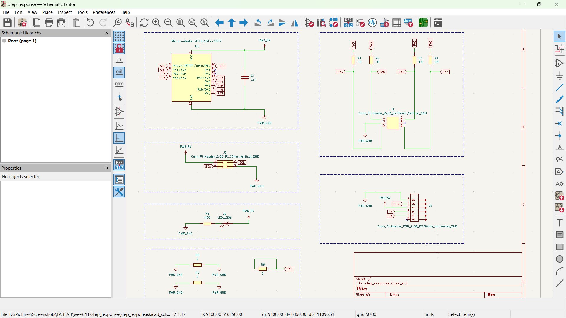
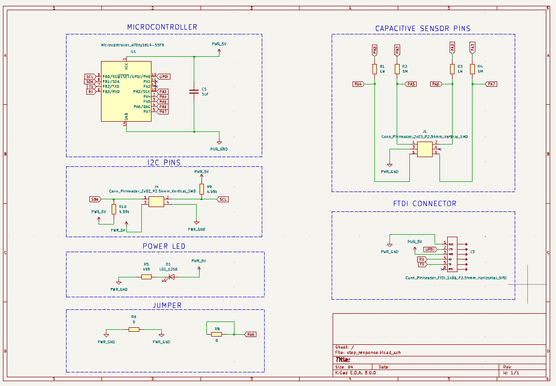
๐Ÿšจ
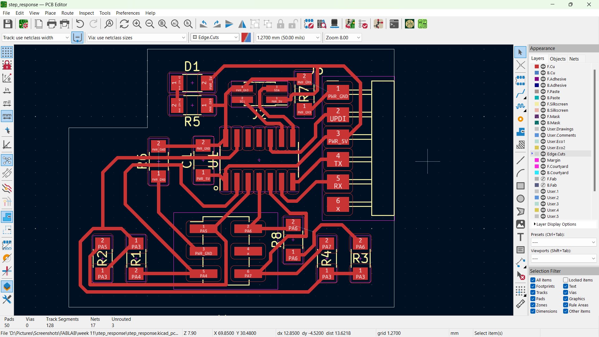
I decided to fabricate a PCB this week. I used KiCad to design my schematic and route the PCB board.
๐Ÿšจ
The image below depicts the schematic of the board.

PCB Routing in KiCad

๐Ÿšจ
The image below depicts the routed PCB board.

Converting Gerber file to PNG

๐Ÿšจ
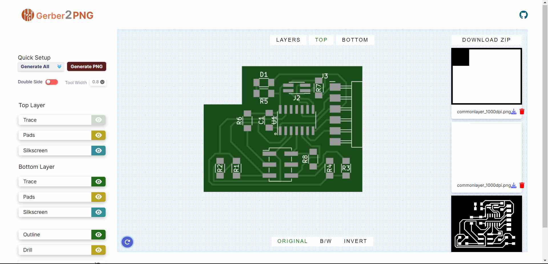
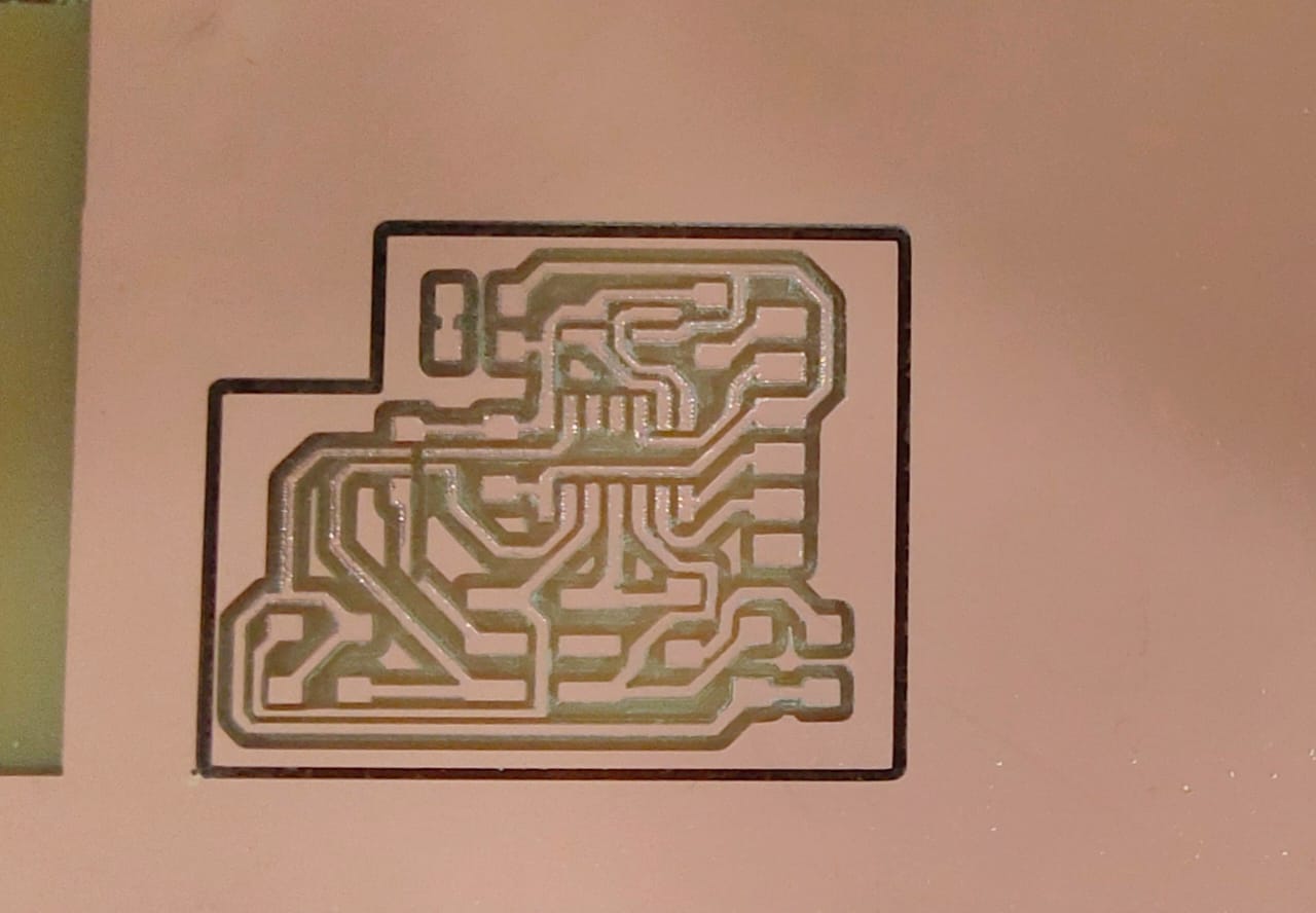
Once I done with the routing the PCB board then I exported the Gerber file from the KiCad and utilized the Gerber2PNG web app to convert the Gerber files into PNG.
โฌ‡๏ธ
To export the Gerber file from KiCad and convert it to PNG, refer to the link below. Make sure to refer to the โ€œGerber File Exportโ€ section.ย 
Rayan Abdul Gafoor - Fab Academy
ยฉ 2024 Rayan Abdul Gafoor. All rights reserved. Students Agreement.
https://fabacademy.org/2024/labs/kochi/students/rayan-abdul/week08.html
โฌ‡๏ธ
Follow the link below to open the Gerber2PNG web app.
Gerber2Png | Fablab Kerala
https://gerber2png.fablabkerala.in/

PCB Milling

โฌ‡๏ธ
Follow the link below to learn more about Electronic Production.
Rayan Abdul Gafoor - Fab Academy
ยฉ 2024 Rayan Abdul Gafoor. All rights reserved. Students Agreement.
https://fabacademy.org/2024/labs/kochi/students/rayan-abdul/week04.html

PCB Soldering

โฌ‡๏ธ
To learn about soldering and the safety measures ๐Ÿฆบ involved, follow the link below.
Rayan Abdul Gafoor - Fab Academy
ยฉ 2024 Rayan Abdul Gafoor. All rights reserved. Students Agreement.
https://fabacademy.org/2024/labs/kochi/students/rayan-abdul/week04.html

Bill of Materials

ReferenceValueQtyDatasheet
C11uF1https://www.yageo.com/upload/media/product/productsearch/datasheet/mlcc/UPY-GP_NP0_16V-to-50V_18.pdf
D1LED_12061https://optoelectronics.liteon.com/upload/download/DS-22-98-0002/LTST-C150CKT.pdf
J1Conn_PinHeader_2x03_P2.54mm_Vertical_SMD1https://cdn.amphenol-icc.com/media/wysiwyg/files/drawing/95278.pdf
J2Conn_PinHeader_2x02_P1.27mm_Vertical_SMD1https://s3.amazonaws.com/catalogspreads-pdf/PAGE94-95%20.050%20MALE%20HDR%20ST%20RA%20SMT.pdf
J3Conn_PinHeader_FTDI_1x06_P2.54mm_Horizontal_SMD1~
R1,R2,R3,R41M4~
R54991~
R6,R7,R803~
U1Microcontroller_ATtiny1614-SSFR1http://ww1.microchip.com/downloads/en/DeviceDoc/ATtiny1614-16-17-DataSheet-DS40002204A.pdf

Interactive BOM

Touchpad Design

๐Ÿšจ
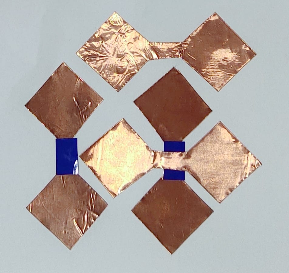
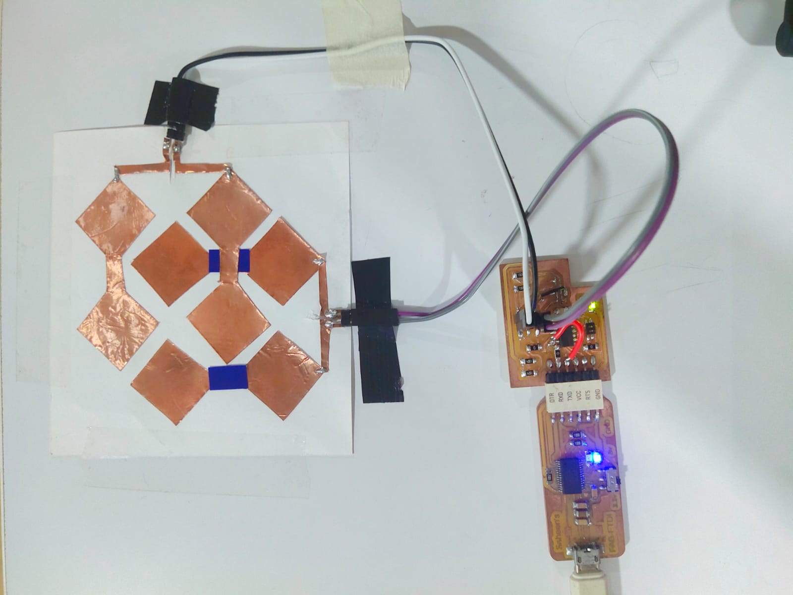
I made the touch pad out of conductive adhesive vinyl and chose a 2-by-2 matrix multitouch pad.
๐Ÿšจ
Below is a picture of the conductive multitouch pad.
โš ๏ธ
Clean the surface of the dielectric material (like a plastic or glass sheet) to ensure good adhesion and no contamination.
โš ๏ธ
Peel the backing off the copper vinyl and carefully stick it onto the dielectric material. Make sure there are no air bubbles or wrinkles. The Dielectric can be air, ceramic, plastic, mica, or other materials.
โš ๏ธ
Ensure each sensor has a separate input and is properly isolated to avoid crosstalk.
๐Ÿšจ
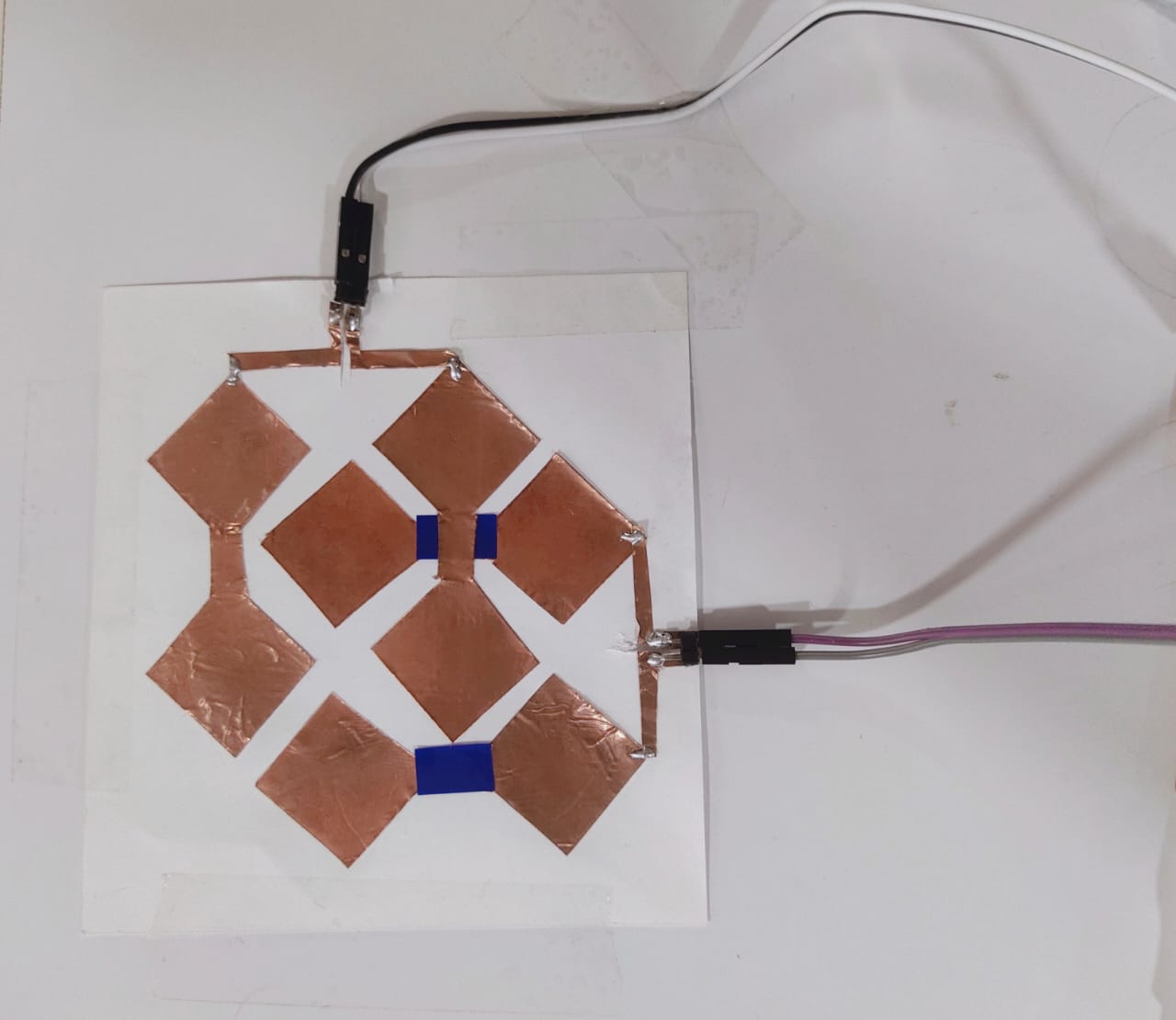
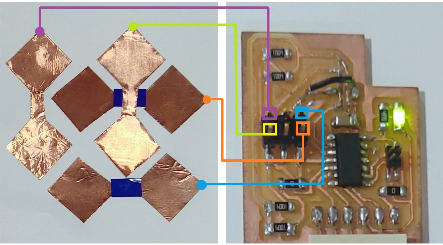
Then I soldered the 1x2 male header pins on the columns and rows. This helps me connect the wires from the touch pad to the PCB I've made this week.

Programming the Board

๐Ÿšจ
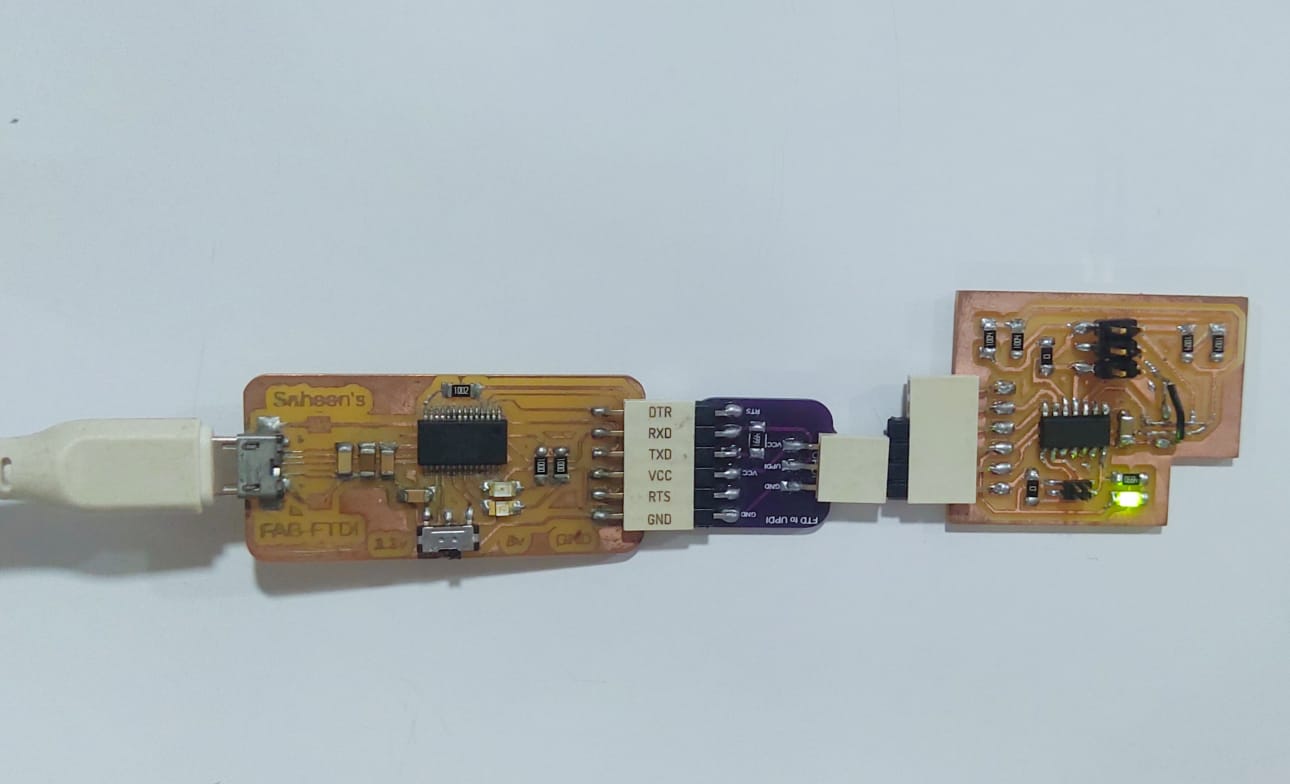
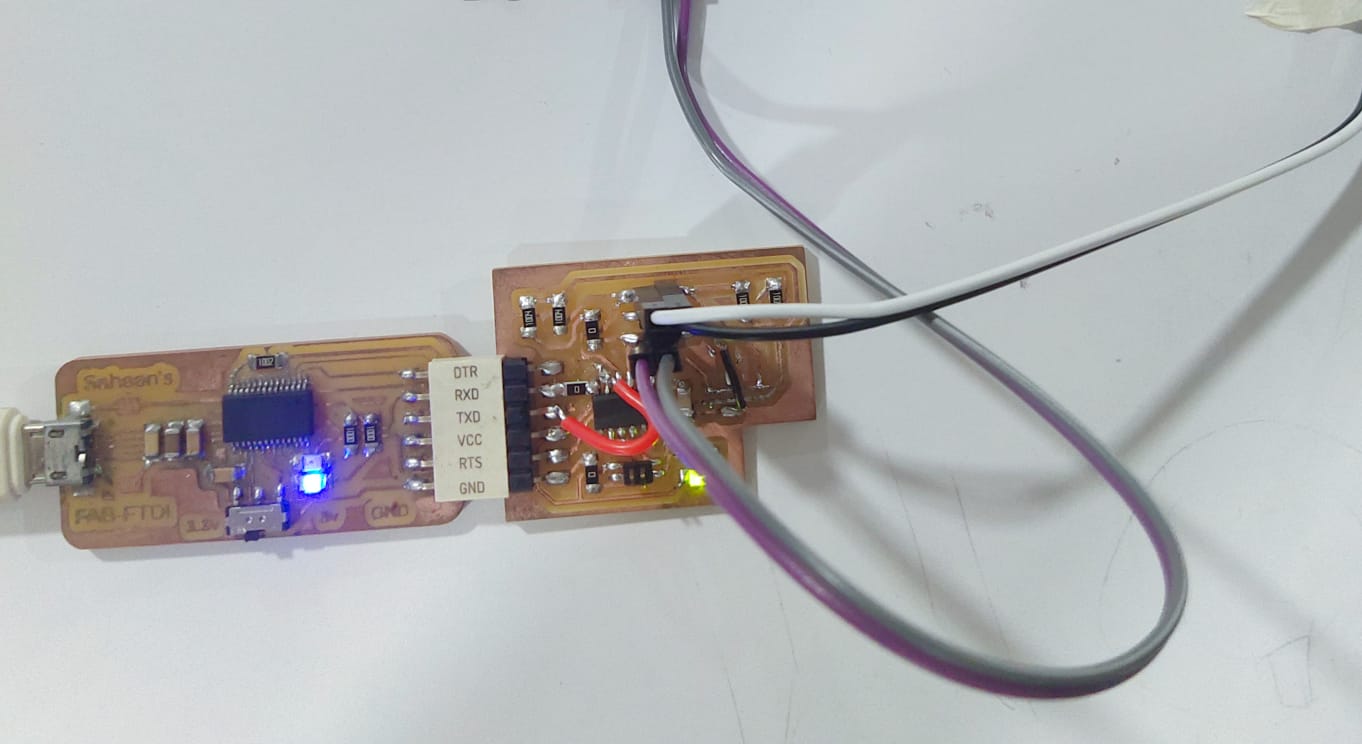
To program the board, I searched ๐Ÿ”ญ my Xiao QT board. However, I couldn't find it at the moment ๐Ÿฅฒ , so I used my instructor's FTDI board instead.
๐Ÿšจ
The ATtiny1614 is programmed using the UPDI pin, So I used the FTDI to UPDI converter.
๐Ÿšจ
The connections are shown below.
๐Ÿšจ
The FTDI board is always in programming mode.
๐Ÿšจ
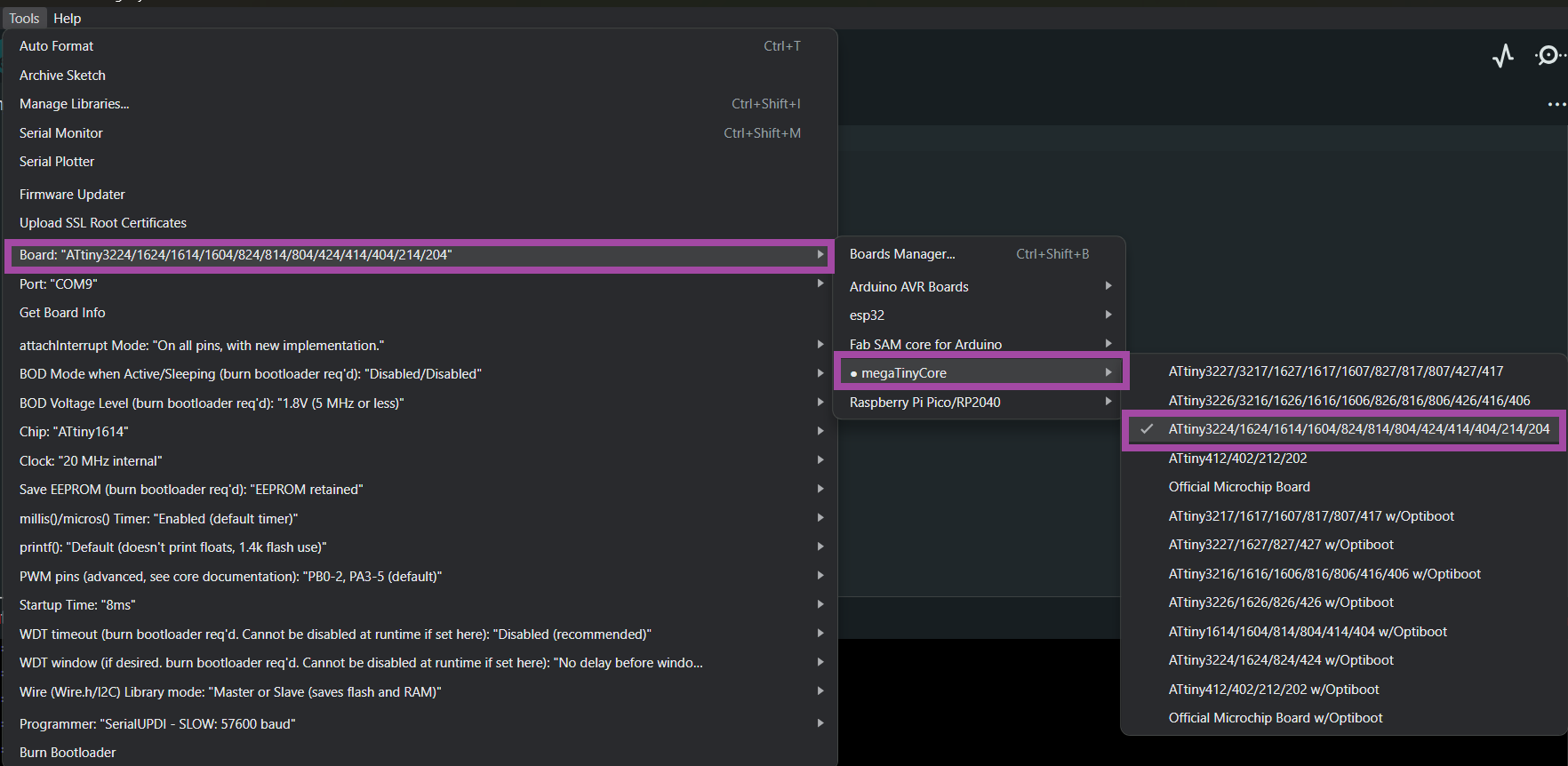
Now from tools , select the board as shown below.
๐Ÿšจ
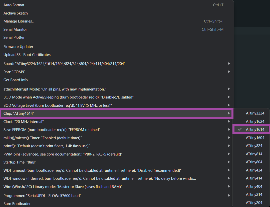
Select the chip as โ€œATtiny1614โ€
๐Ÿšจ
Select the programmer.
๐Ÿšจ
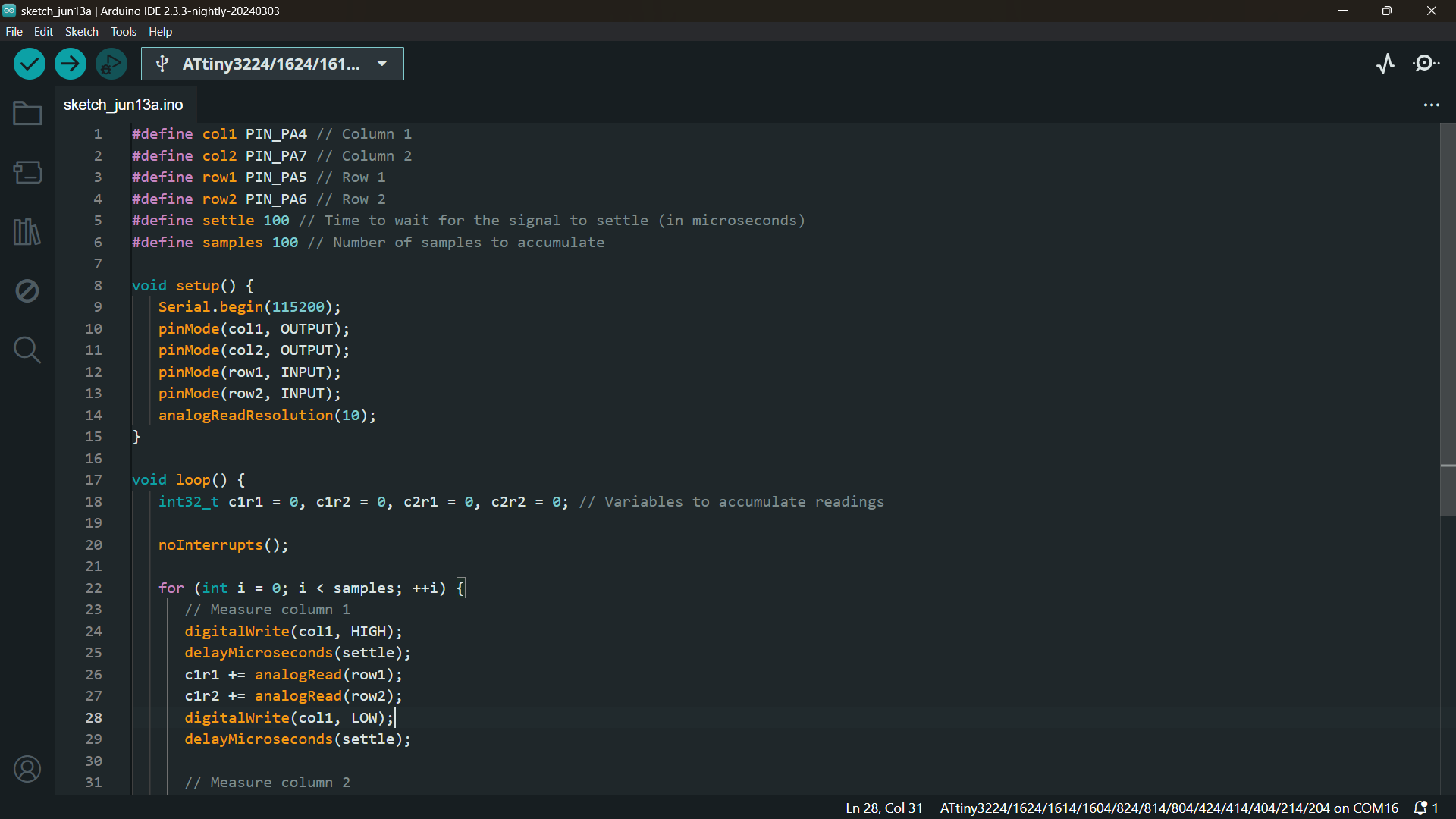
Now write your required embedded program in the Arduino IDE and compile the code to resolve the errors.
๐Ÿšจ
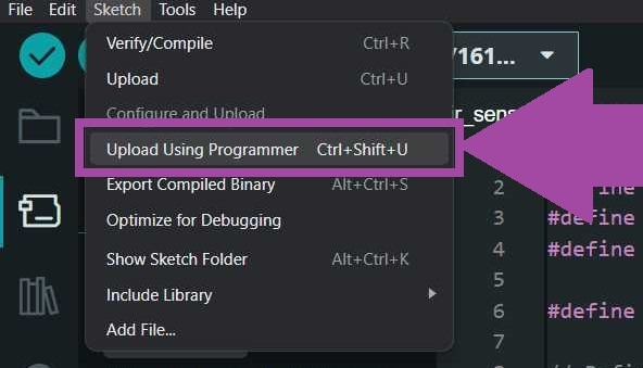
To upload the code to the ATtiny1614, go to โ€œSketchโ€ and select โ€œUpload Using Programmerโ€ or press โ€œCtrl+Shift+Uโ€.

Access Data Serially

๐Ÿšจ
After successfully uploading the program, disconnect the FTDI to UPDI converter and directly connect the programmer to the board, as illustrated below. This allows me to read data (and/or write data) from the microcontroller via serial.
๐Ÿšจ
The image below illustrates the connection between the touchpad and the board.

Embedded Program

๐Ÿšจ
Upload this code into the microcontroller using the โ€œUpload Using the Programmerโ€ option.
// Define pin assignments for columns and rows
#define col1 PIN_PA4 // Column 1
#define col2 PIN_PA7 // Column 2
#define row1 PIN_PA5 // Row 1
#define row2 PIN_PA6 // Row 2

// Define constants for signal settling time and number of samples
#define settle 100 // Time to wait for the signal to settle (in microseconds)
#define samples 100 // Number of samples to accumulate

void setup() {
   Serial.begin(115200); // Initialize serial communication at 115200 baud rate
   pinMode(col1, OUTPUT); // Set column 1 pin as output
   pinMode(col2, OUTPUT); // Set column 2 pin as output
   pinMode(row1, INPUT); // Set row 1 pin as input
   pinMode(row2, INPUT); // Set row 2 pin as input
   analogReadResolution(10); // Set analog read resolution to 10 bits
}

void loop() {
   // Initialize variables to accumulate readings for each column-row combination
   int32_t c1r1 = 0, c1r2 = 0, c2r1 = 0, c2r2 = 0;

   noInterrupts(); // Disable interrupts to ensure accurate timing for measurements
   
   for (int i = 0; i < samples; ++i) {
      // Measure signals for column 1
      digitalWrite(col1, HIGH); // Set column 1 HIGH
      delayMicroseconds(settle); // Wait for the signal to settle
      c1r1 += analogRead(row1); // Read analog value from row 1 and accumulate
      c1r2 += analogRead(row2); // Read analog value from row 2 and accumulate
      digitalWrite(col1, LOW); // Set column 1 LOW
      delayMicroseconds(settle); // Wait for the signal to settle

      // Measure signals for column 2
      digitalWrite(col2, HIGH); // Set column 2 HIGH
      delayMicroseconds(settle); // Wait for the signal to settle
      c2r1 += analogRead(row1); // Read analog value from row 1 and accumulate
      c2r2 += analogRead(row2); // Read analog value from row 2 and accumulate
      digitalWrite(col2, LOW); // Set column 2 LOW
      delayMicroseconds(settle); // Wait for the signal to settle
   }
   
   interrupts(); // Re-enable interrupts

   // Print the accumulated readings for each column-row combination
   Serial.print("C1R1: ");
   Serial.print(c1r1);
   Serial.print(", C1R2: ");
   Serial.print(c1r2);
   Serial.print(", C2R1: ");
   Serial.print(c2r1);
   Serial.print(", C2R2: ");
   Serial.println(c2r2);
   
   Serial.flush(); // Ensure all serial data is transmitted before continuing
}

โš ๏ธ Calibrate the Sensor

โš ๏ธ
Test the sensor by touching or bringing objects close to the copper vinyl. Observe the readings from the microcontrollerโ€™s serial output.
โš ๏ธ
Adjust the sensitivity and thresholds in your code based on the readings to fine-tune the sensorโ€™s responsiveness.

Creating the GUI for the Capacitive Multitouch Pad
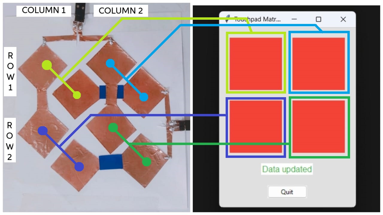
๐Ÿšจ
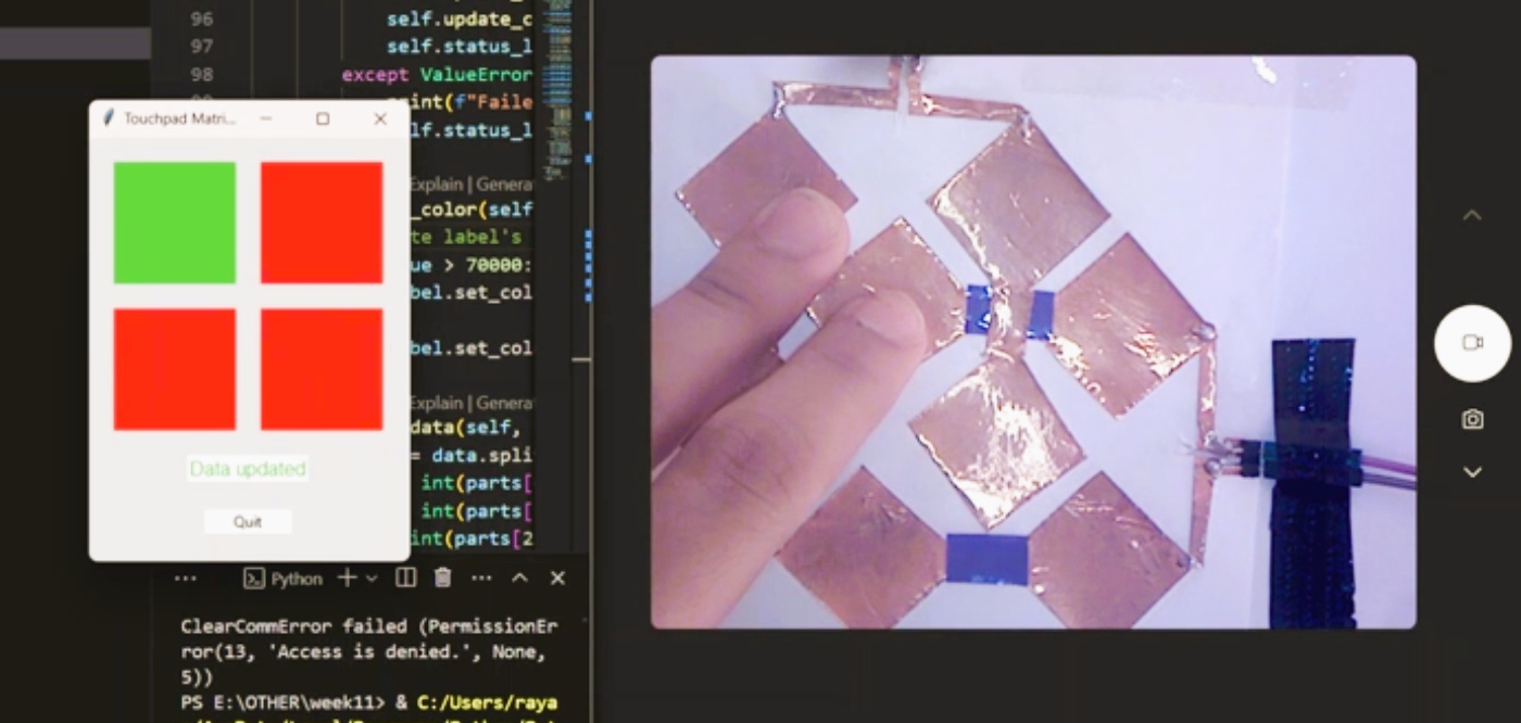
To create the GUI for the capacitive multitouch pad, I used the Python tkinter library. The GUI displays color-coded rectangles that change their color based on the values received from a serial port connection to the multitouch pad. This provides a visual representation of the touchpad's sensor data, indicating the touch intensity with color changes.
๐Ÿšจ
I have utilized ChatGPT to generate a rough code, and I work on top of it to debug and execute the code as per my needs.ย 
๐Ÿšจ
The image below illustrates the multitouch pad and the GUI.

Overview of the Implementation

๐Ÿ’ 
The data received from the serial port is expected in a specific format. This data is parsed to extract touch intensity values for each sensor region of the touchpad.
๐Ÿ’ 
The GUI is created using tkinter, with a grid layout to arrange the color-coded rectangles. Each rectangle corresponds to a specific sensor region on the touchpad.
๐Ÿ’ 
Based on the parsed touch intensity values, the color of each rectangle is updated. Values above a certain threshold change the color to green, indicating a high touch intensity, while values below the threshold keep the color red, indicating a low touch intensity.
๐Ÿ’ 
The GUI includes a status label that provides feedback on data updates and a quit button to safely terminate the application and close the serial connection.

GUI Code

import tkinter as tk
from tkinter import ttk
import serial
import threading

# Define the serial port and baud rate
SERIAL_PORT = 'COM17'
BAUD_RATE = 115200

# Class to handle serial communication
class SerialReader:
    def __init__(self, port, baudrate):
        # Initialize the serial port
        self.serial_port = serial.Serial(port, baudrate, timeout=1)
        self.is_running = False
        self.thread = None

    def start_reading(self, callback):
        # Start the thread to read serial data
        self.is_running = True
        self.thread = threading.Thread(target=self.read_serial, args=(callback,))
        self.thread.start()

    def stop_reading(self):
        # Stop the thread reading serial data
        self.is_running = False
        if self.thread is not None:
            self.thread.join()

    def read_serial(self, callback):
        # Continuously read from the serial port and call the callback with the data
        while self.is_running:
            if self.serial_port.in_waiting > 0:
                data = self.serial_port.readline().decode().strip()
                if data:
                    callback(data)

    def close(self):
        # Close the serial port
        self.serial_port.close()

# Custom frame to represent a color-changing rectangle
class RectangleLabel(ttk.Frame):
    def __init__(self, parent, width=50, height=50, bg="red", **kwargs):
        super().__init__(parent, **kwargs)
        self.width = width
        self.height = height
        self.bg = bg

        # Create a canvas to draw the rectangle
        self.canvas = tk.Canvas(self, width=self.width, height=self.height, bg=self.bg, highlightthickness=0)
        self.canvas.pack(fill=tk.BOTH, expand=True)

    def set_color(self, color):
        # Change the color of the rectangle
        self.canvas.config(bg=color)

# Main application class
class App:
    def __init__(self, root):
        self.root = root
        self.root.title("Touchpad Matrix GUI")
        self.root.geometry("500x500")  # Set square size of the window

        # Configure styles for better appearance
        self.style = ttk.Style()
        self.style.configure('TFrame', background='#e0e0e0')  # Set background color for frames
        self.style.configure('TLabel', background='#ffffff', foreground='#333333', font=('Arial', 12))  # Set label styles
        self.style.map('TButton', background=[('active', '#ffc107')])  # Button color change on click

        # Initialize the serial reader
        self.serial_reader = SerialReader(SERIAL_PORT, BAUD_RATE)

        self.create_widgets()
        # Start reading from the serial port
        self.serial_reader.start_reading(self.update_display)

    def create_widgets(self):
        # Create a frame to hold the widgets
        self.frame = ttk.Frame(self.root, padding="10")
        self.frame.grid(row=0, column=0, sticky=(tk.W, tk.E, tk.N, tk.S))

        # Create rectangle labels for the touchpad matrix
        self.c1r1_label = RectangleLabel(self.frame, width=100, height=100, bg="red")
        self.c1r1_label.grid(row=0, column=0, padx=10, pady=10)

        self.c1r2_label = RectangleLabel(self.frame, width=100, height=100, bg="red")
        self.c1r2_label.grid(row=1, column=0, padx=10, pady=10)

        self.c2r1_label = RectangleLabel(self.frame, width=100, height=100, bg="red")
        self.c2r1_label.grid(row=0, column=1, padx=10, pady=10)

        self.c2r2_label = RectangleLabel(self.frame, width=100, height=100, bg="red")
        self.c2r2_label.grid(row=1, column=1, padx=10, pady=10)

        # Add a status label to show updates
        self.status_label = ttk.Label(self.frame, text="Waiting for data...", style='TLabel')
        self.status_label.grid(row=2, column=0, columnspan=2, pady=10)

        # Add a quit button to close the application
        self.quit_button = ttk.Button(self.frame, text="Quit", command=self.quit)
        self.quit_button.grid(row=3, column=0, columnspan=2, pady=10)

    def update_display(self, data):
        try:
            # Parse the received data
            c1r1, c1r2, c2r1, c2r2 = self.parse_data(data)
            # Update the color of the rectangles based on the data
            self.update_color(self.c1r1_label, c1r1)
            self.update_color(self.c1r2_label, c1r2)
            self.update_color(self.c2r1_label, c2r1)
            self.update_color(self.c2r2_label, c2r2)
            self.status_label.config(text="Data updated", foreground="#4caf50")  # Bright green color
        except ValueError:
            print(f"Failed to parse data: {data}")
            self.status_label.config(text="Error: Failed to parse data", foreground="#f44336")  # Bright red color

    def update_color(self, label, value):
        # Update the label's background color based on the value
        if value > 70000:
            label.set_color("#4caf50")  # Bright green color
        else:
            label.set_color("#f44336")  # Bright red color

    def parse_data(self, data):
        # Parse the received data assuming format "C1R2: value, C1R1: value, C2R2: value, C2R1: value"
        parts = data.split(',')
        c1r2 = int(parts[0].split(':')[1].strip())
        c1r1 = int(parts[1].split(':')[1].strip())
        c2r2 = int(parts[2].split(':')[1].strip())
        c2r1 = int(parts[3].split(':')[1].strip())
        return c1r1, c1r2, c2r1, c2r2

    def quit(self):
        # Stop reading from the serial port and close the application
        self.serial_reader.stop_reading()
        self.serial_reader.close()
        self.root.destroy()

# Main function to start the application
def main():
    root = tk.Tk()
    app = App(root)
    root.mainloop()

# Entry point of the application
if __name__ == "__main__":
    main()

Explanation of the Python Code

๐Ÿ“‹
SerialReader Class: Handles serial communication, including starting and stopping a reading thread.
๐Ÿ“‹
RectangleLabel Class: Custom frame with a color-changing rectangle.
๐Ÿ“‹
App Class: Manages the main GUI, including widget creation, serial data handling, and GUI updates.
๐Ÿ“‹
main Function: Initializes and starts the tkinter main loop.

Final Result ๐Ÿ˜€๐Ÿ˜€๐Ÿ˜€

Challenges โšกโšกโšก

โšก
This week I have encountered a few challenges, which I have mentioned below.

Changed the SMT header pins

โš ๏ธ
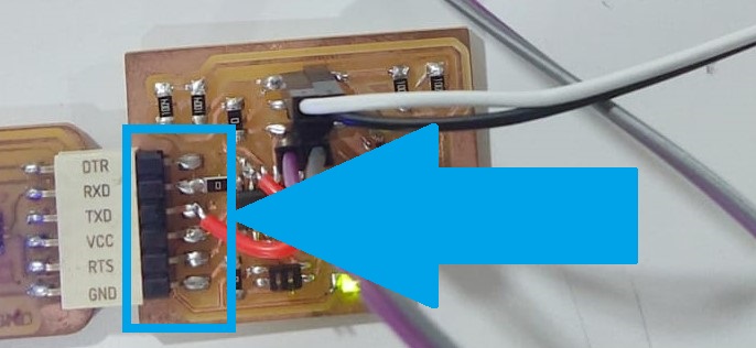
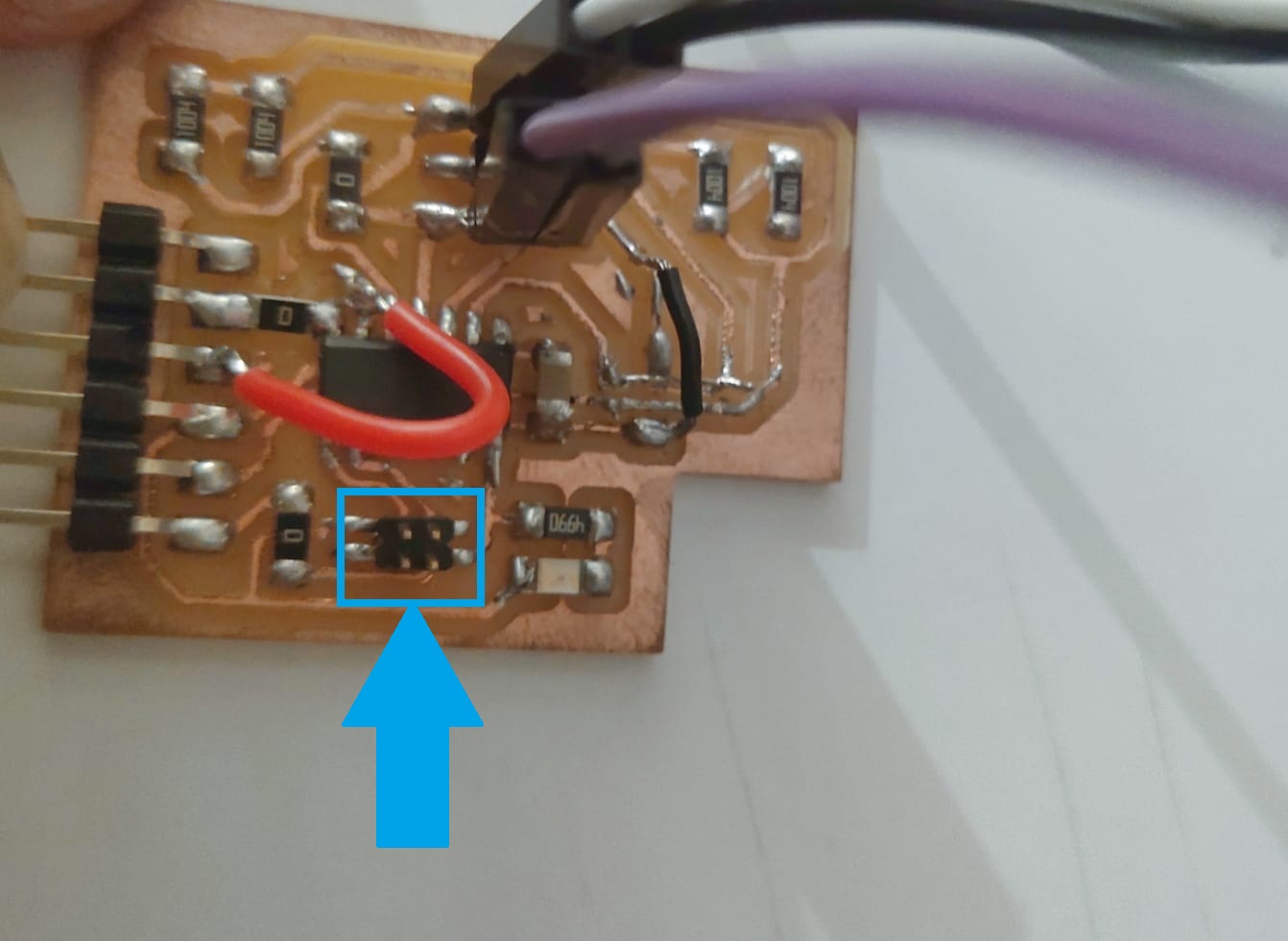
Initially, I soldered the SMT female header pins for the FTDI. The FTDI programmer with me also has female pins, so I disordered and connected the horizontal SMT male connector as shown below.ย 
โš ๏ธ
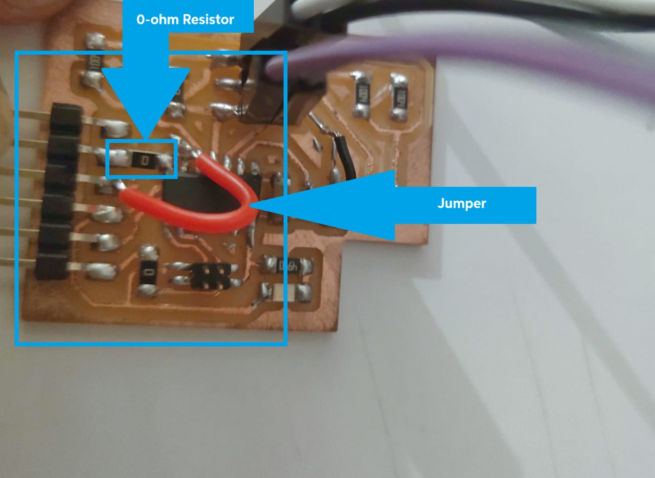
While checking the routing, I found that the rx and tx are connected directly, so I used a jumper wire and a zero-ohm resistor to rectify this issue.
โš ๏ธ
While drawing the schematic, I chose the wrong pitch header pins. Instead of 2.54mm, I chose a 1.27mm header pin for the I2C. However, I am not using it this week. My plan was to use this board as a node for the networking and communication week.

Group Assignment Page

๐Ÿ“Œ
For the group assignment page click here.

Reference

Matt Blackshaw - How to Make (Almost) Anything
This week I made a capacitive touchpad with an ATTiny44 micro controller which measures input voltage on a number of copper pads using step response.
https://fab.cba.mit.edu/classes/863.10/people/matt.blackshaw/week8.html
Capacitive Multitouch
For this week's assignment, I made a 4x4 capacitive multitouch grid. Designs like the $4 touchpad are limited to a single touch - with multiple touches, it is impossible to tell which row is associated with which column (unless you do sneaky things with mutual capacitance, which is a whole 'nother barrel of fish).
https://fab.cba.mit.edu/classes/863.11/people/matthew.keeter/multitouch/index.html
10. input devices - Arman Najari Fab Academy
The sensor that I chose to work with is the capacitive sensing. I really fascinated by the simplicity of the system and complexity of the applications. I would like to develop a touch interface embedded in my final project as the interface of the machine. I would try to push this week to finish at least the design of the board.
https://fabacademy.org/2020/labs/barcelona/students/arman-najari/assignments/week10/

Resources and Downloads

๐Ÿ“ KiCad file

๐Ÿ“ Gerber 2 PNG file

๐Ÿ“ Microcontroller Code

๐Ÿ“ GUI Code